
Updated:2025-01-09
The motor controller is one of the key components of the electric control system in new energy vehicles. It is responsible for converting the direct current from the battery into alternating current to drive the motor. In this process, the core power devices are generally MOSFETs or IGBTs made of SiC or GaN materials, which undertake the tasks of energy conversion and power control. To ensure the performance and reliability of the motor controller, it is necessary to conduct rigorous tests on these power devices, including double pulse tests.
Case Introduction
Double pulse tests can help engineers evaluate key parameters of power devices in motor controllers, such as switching speed, switching loss, voltage and current waveforms, thereby optimizing the design of the motor controller. However, measuring the upper tube Vgs in the double pulse test is a technical challenge. It requires the measurement system to not only have high bandwidth characteristics but also higher common mode rejection capabilities.
Test Example
Device Under Test: Core board of a certain new energy vehicle motor controller
Test Points: Upper tube Vgs and upper tube Vds in the bridge circuit of the motor controller
Customer Pain Point: When using traditional differential probes to measure the upper tube Vgs before, there was serious signal oscillation, making it impossible to analyze and locate circuit problems.
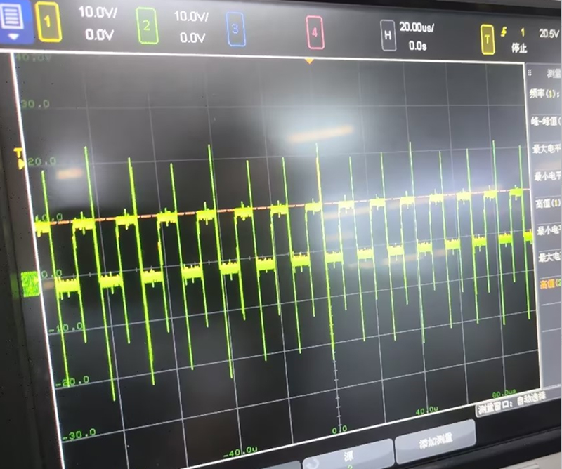
▲ Original test signal oscillation distortion
Test Site
The following on-site test diagram shows Micsig's high-resolution oscilloscope MHO3 series MHO3-5004, optical isolation probe MOIP series MOIP1000P, high-voltage differential probe DP1502, and the device under test.
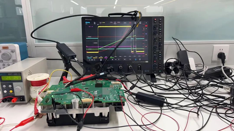
▲ On-site test diagram
In the double pulse test, the optical isolation probe measures the upper tube Vgs. This module is the core part of the motor controller, and its switching speed is very fast, usually at the nanosecond level. During the test, the electromagnetic interference (EMI) generated by high-speed switching will affect the measurement results. The high common mode rejection ratio of the optical isolation probe can reveal the entirety of the signal's truth, providing clear signal waveforms even in high interference environments.
The interference of the lower tube is relatively less severe, so differential probes can meet the test requirements. Currently, the mainstream double pulse test uses differential probes with a bandwidth of 200MHz and an isolation of 1500V. Since the device's pins are relatively thin, traditional current measurement methods may not be able to directly measure the thinner chip pins. Therefore, it is recommended to use a Rogowski coil to test the lower tube Id. The Rogowski coil is a non-contact current measurement device that can measure current without touching the wire, which is crucial for protecting the pins and quickly and conveniently obtaining accurate current measurement results.
Let's take a look at the actual measurement waveforms, as shown in the following figure: The optical isolation probe measures the upper tube Vgs, the differential probe measures the lower tube Vds and lower tube Vgs, and it is recommended to use Micsig's Rogowski coil RCP1200XS to measure the lower tube Id.
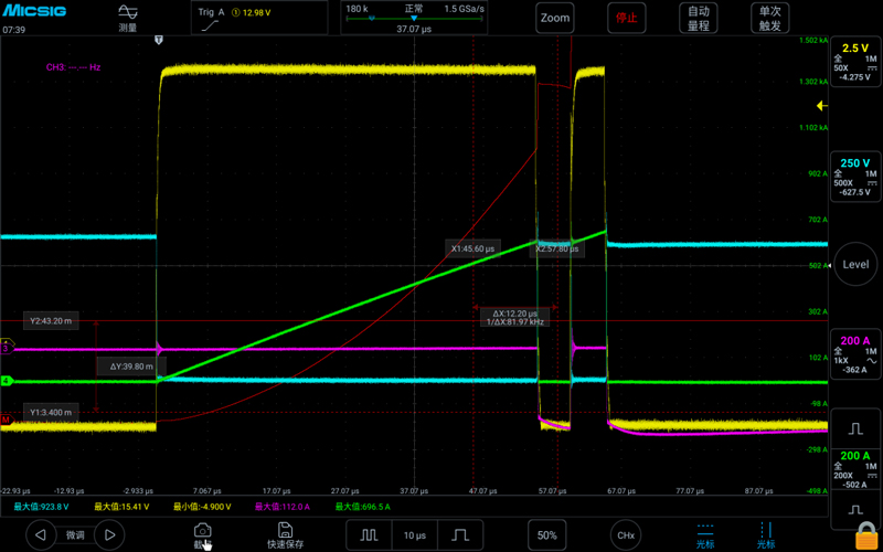
▲ Actual measurement waveform diagram
Customer Feedback
In the previous double pulse tests, there was significant common mode interference in the upper tube Vgs signal. At first, the understanding of the common mode rejection ratio (CMRR) of differential probes was not deep enough, and the test results of differential probes were always believed. It was thought that the oscillation was caused by the system design, and the circuit was repeatedly modified and verified, but the problem was still not solved. This time, after using Micsig's optical isolation probe, the test effect is very good. This optical isolation probe still has a high CMRR in the high-frequency band, and the oscillation waveform disappears after the test. The result is very similar to our theoretical analysis.
Summary
Micsig's optical isolation probe MOIP1000P has a common mode rejection ratio as high as 180dB, and can still maintain a performance of more than 100dB at 1GHz frequency band. This excellent performance enables the probe to conduct more accurate and reliable circuit testing and verification in circuit designs with silicon carbide (SiC) and gallium nitride (GaN) as core devices. It allows engineers to capture the real upper tube Vgs voltage waveform, thereby accurately analyzing whether the circuit design meets the requirements and ensuring the high performance and reliability of the product.
About Micsig
Shenzhen Micsig Technology Co., Ltd. is a leading R&D manufacturer and solution provider of signal testing and measurement equipment, a national high-tech enterprise, and a specialized, refined, and innovative enterprise. Micsig is committed to the research and development of cutting-edge technologies in the field of signal testing and measurement, especially in the field of oscilloscopes and oscilloscope probes, we have always been at the forefront of innovation. We are the pioneers of flat panel oscilloscopes and the leaders of optical isolation probes.
We adhere to our mission and vision, starting from professionalism, and continuously break through the technical boundaries to help every worker in the electronic field and their organizations to be more efficient and excellent.
Every innovation of ours is only for breaking through the technical boundaries of products and exploring new possibilities for the development trend of the industry.
The company's main products include oscilloscope series: high-resolution oscilloscopes, flat panel oscilloscopes, automotive diagnostic oscilloscopes, split oscilloscopes, and oscilloscope probe series: optical isolation probes, high-voltage differential probes, flexible current probes (Rogowski coils), high-frequency AC/DC current probes, low-frequency AC/DC current probes, etc.