
Updated:2024-10-18
In the realm of electronic testing and measurement, the precise capture of electrical signals is the key to success. However, real-world scenarios are often complex and variable, with signals inevitably subjected to various interferences during transmission. This article will explore the differences between common-mode and differential-mode signals, as well as the importance of the Common Mode Rejection Ratio (CMRR). We will explain these concepts and demonstrate how Micsig's SigOFIT optically isolated probes showcase their unparalleled common-mode rejection capability in the measurement of GaN half-bridge circuits. Through practical examples, we will reveal the sources of common-mode interference and how probes with a high CMRR value can effectively suppress these interferences, thereby enhancing the signal-to-noise ratio and the accuracy of measurements.
Common-Mode and Differential-Mode Signals
Micsig's SigOFIT optically isolated probes have many advantages over differential probes, one of the most important being their unmatched common-mode rejection capability. So, what is the use of a strong common-mode rejection capability? In electronics, signals can be divided into two basic modes: common-mode and differential-mode. These two modes are crucial for understanding signal transmission and interference handling, especially in areas involving signal integrity and noise suppression. With questions in mind, let's first look at what exactly are common-mode signals and differential-mode signals.
What is Common-Mode Signal
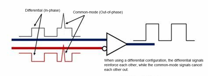
Common-mode signals refer to the signal components that have the same amplitude and phase on two signal lines relative to a reference point (usually ground). In simple terms, common-mode signals are the common variation parts of the two signal lines relative to a common reference point.
What is Differential-Mode Signal
Differential-mode signals refer to the voltage difference between two signal lines, that is, the relative change between the two lines. It is the effective signal component that is actually transmitted, representing the information transfer between the signal lines.
Regarding Common Mode Rejection Ratio (CMRR)
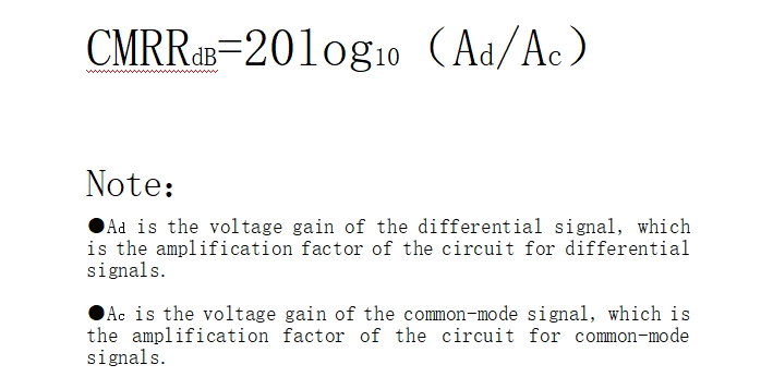
The CMRR of a probe is an important parameter for the voltage probe's amplification capability for differential signals and its suppression capability for common-mode signals (interference signals). In an ideal situation, the amplification circuit should only amplify the differential signal (i.e., the signal difference between the two input ends) and be completely insensitive to the common-mode signal (i.e., the same signal on both input ends). The larger the CMRR value, the stronger the circuit's suppression capability for common-mode signals, and usually, the better the circuit's performance.
CMRR is usually represented in units of dB, and its calculation formula is as follows:
If the gain of the probe device for the differential signal is 1000 (30 dB), and the gain for the common-mode signal is 1 (0 dB), then the CMRR will be:
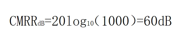
The larger the CMRR value, the smaller the amplification multiplier of the probe for the common-mode signal, thus the stronger the suppression capability for common-mode interference. In electronic measurement and signal processing, a high CMRR helps to improve the signal-to-noise ratio and reduce the impact of interference on measurement results.
GaN Half-Bridge Circuit Analysis
Let's take the measurement of the upper tube Vgs in a GaN half-bridge circuit as an example. The Vgs drive signal of the upper tube is the differential-mode signal, and the Vds of the lower tube is the common-mode signal.
In GaN half-bridge circuits, especially when it comes to measuring the gate-source voltage (Vgs) of the upper tube, common-mode interference is a common issue. This interference may come from various sources and can adversely affect the measurement results.
In GaN half-bridge circuits, the transient voltage during switching is very high, especially during high-speed switching operations. When the upper and lower tubes alternately conduct, high-frequency common-mode voltage is generated at the gate-source due to the rapid voltage changes during the switching process; rapid switching changes also generate strong electromagnetic fields around the half-bridge circuit, which can induce common-mode voltage in nearby conductors. At the switching instant, electromagnetic radiation may couple into the gate-source loop, forming common-mode interference.
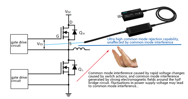
Measurement equipment introduces common-mode interference
In high-speed switching applications, long conductors may collect electromagnetic field energy from the surroundings like antennas, thereby generating common-mode voltage. The input capacitance and input resistance of the measurement probe may form a voltage-dividing network with the circuit, leading to common-mode interference. Differential probes may have these issues, while Micsig's optically isolated probes can use MMCX or MCX connectors with extremely short leads and very low input capacitance, avoiding these problems.
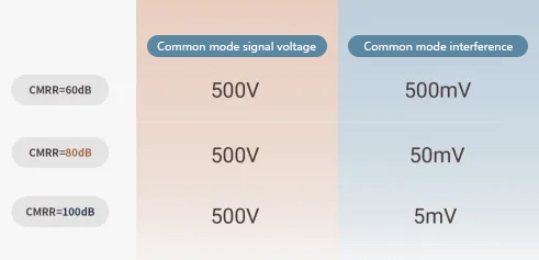
Such a large amount of common-mode interference can seriously affect the results of signal measurement. Therefore, our test probes must have a strong ability to suppress common-mode interference to ensure the authenticity of the signal. The larger the CMRR, the stronger the ability to suppress common-mode noise. Assuming testing of a GaN circuit, the common-mode signal voltage is 500V, dv/dt=250V/ns, to suppress such common-mode interference, if CMRR=60dB, the probe will output 500mV of common-mode interference superimposed on the differential-mode signal, which obviously affects the differential-mode signal. If CMRR=80dB, the probe will superimpose 50mV of common-mode interference on the differential-mode signal, which is still not negligible for the differential-mode signal. If CMRR=100dB, the probe will only retain 5mV of common-mode interference, which can be completely ignored for the differential-mode signal.
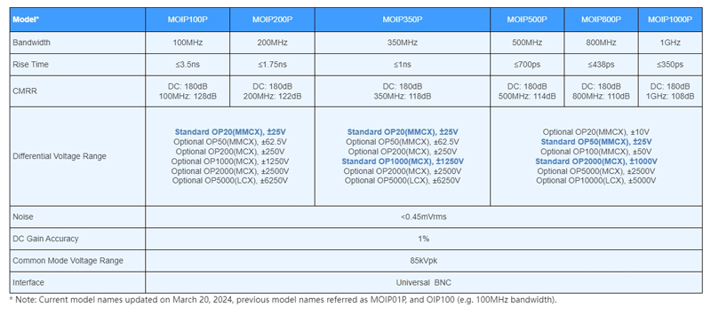
Micsig's SigOFIT optically isolated probe has a CMRR as high as 180dB, and still has a CMRR of over 100dB at the 1GHz frequency band, which can almost perfectly suppress the oscillations caused by high-frequency common-mode noise, and the presented signal has no additional redundant components, making it the best choice for the testing of the third-generation semiconductor. In addition, in high-speed signal transmission, if the impedance of the signal line does not match, it may cause signal reflection, thereby generating common-mode voltage. This reflection phenomenon will exacerbate the problem of common-mode interference. Micsig's SigOFIT optically isolated probe adopts 50Ω impedance, which can minimize signal reflection and provide better signal integrity.
Summary
Through the above article, we have learned what common-mode and differential-mode are, as well as some of the causes of common-mode interference. At the same time, Micsig's SigOFIT optically isolated probe has an ultra-high common-mode rejection ratio, which can better suppress common-mode noise and ensure the integrity of the signal, helping us to see the true nature of the signal and assisting everyone in completing the measurement of gate voltage drive of high-voltage and high-frequency challenging scenarios such as SiC/GaN power devices. If you have any purchase or sample request needs, please feel free to contact us.