Updated:2024-07-12
Optical isolated probes are mainly used for testing high-voltage and high-frequency circuits composed of power semiconductors, such as switch-mode power supplies, inverters, chargers, frequency converters, motor drives, and especially for bridge circuits comprising wide-bandgap semiconductor devices like GaN and SiC devices.
So why are optical-fiber isolated probes used in these fields?

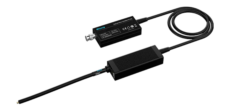
Micsig SigOFIT optical-fiber isolated probe
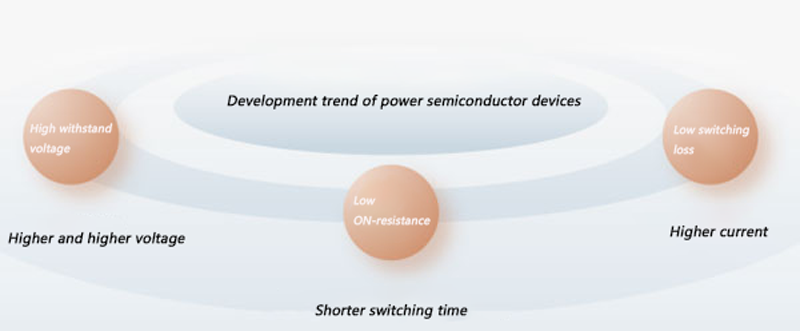
In these fields, a common characteristic is high voltage slew rate (dv/dt). Traditional high-voltage circuits test is generally achieved using high-voltage differential probes. However, these probes often exhibit significant shortcomings in common-mode rejection ratio (CMRR), isolation voltage, signal-to-noise ratio (SNR), bandwidth and bandwidth flatness, and immunity to interference. Power semiconductor devices have been continuously evolving towards higher voltage tolerance, lower on-state resistance, and reduced switching losses. From the perspective of final circuit performance, this means increasing voltage levels, faster on/off switching time, and higher current flow.

Development direction of power semiconductor devices
High-voltage differential probes are essentially incapable of handling such testing tasks, whereas optical isolated probes' excellent performance completely compensates for the shortcomings of high-voltage differential probes.
However, whether high-voltage differential probes or optical isolated probes, some engineers have misconceptions, such as misunderstanding the relationship between differential voltage and common-mode voltage.
Differential Voltage and Common-Mode Voltage
Some engineers believe that optical isolated probes can withstand tens of thousands of volts of common-mode voltage, therefore they can measure differential voltages of tens of thousands of volts.
Common-Mode Voltage: Common-mode voltage is relative to the probe; this voltage is generally referenced to ground. When both positive and negative input terminals of the probe are floating at the ground voltage, that is the common-mode voltage. The indicated common-mode voltage of the probe is the maximum isolation voltage of the probe. For safety reasons, the isolation voltage of the probe must be higher than the highest voltage of the circuit under test, to protect personnel and equipment. The higher the allowed common-mode voltage of the probe, the better.
Differential Voltage: Differential voltage is the signal voltage that the probe needs to measure.

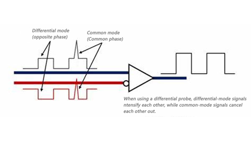
Common Mode and Differential Mode
The maximum measurable common-mode input voltage for high-voltage differential probes is also the maximum common-mode voltage of the differential probe, typically ranging from hundreds of volts to thousands of volts, which is related to the circuit principles of high-voltage differential probes. In some cases, the common-mode voltage and differential voltage of high-voltage differential probes are contradictory. Engineers aim for a higher common-mode voltage to ensure safety, while also desiring high signal-to-noise ratio when testing different range of differential signals. However, the hardware attenuation ratio of high-voltage differential probes cannot be changed, so the signal-to-noise ratio also decreases synchronously when the amplitude of the differential signal is low. Optical isolated probes, due to their optoelectronic isolation, can handle common-mode voltages up to tens of thousands of volts, and can adapt differential voltages from millivolts to several thousand volts using different attenuators, maintaining high signal-to-noise ratios.
Summary:
1. Common-mode voltage ≠ differential voltage; optical isolated probes has much higher common-mode voltage.
2. By swapping attenuators with different attenuation ratios to flexibly adapt differential voltages, maintaining a higher signal-to-noise ratio, this is an acquired advantage of optical isolated probe.

