One Article to know High-Resolution Modular Oscilloscope MO3 Series
Release Time:2026-09-02
In power electronics, industrial control, communications R&D, and automated testing, engineers are often faced not only with high-speed signals, but also with weak ripple, occasional glitches, multi-channel timing relationships, and abnormal states that occur during long-duration operation.
The Micsig MO3 series high-resolution modular oscilloscope integrates 12-bit high-resolution acquisition, deep memory, multi-unit synchronization, protocol decoding, and automation integration capabilities into a compact chassis just 30 mm high. It can serve as a precision measurement instrument in the lab, and can also be flexibly deployed in racks and automated test systems.
1. Key Specifications
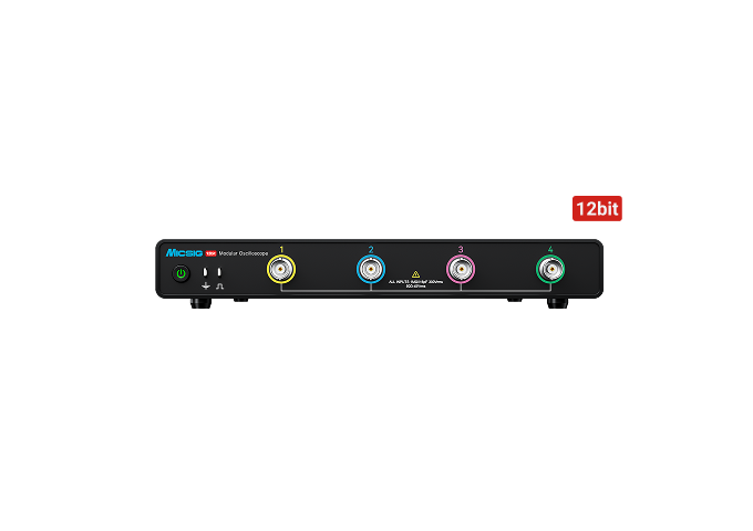
Fig. 1 Front view of the MO3 series (12-bit badge)
Model | MO34-250 / 250Pro | MO34-350 / 350Pro | MO34-500 / 500Pro |
Analog Bandwidth | 250 MHz | 350 MHz | 500 MHz |
Rise Time | ≤1.4 ns | ≤1 ns | ≤0.7 ns |
Analog Channels | 4 CH | 4 CH | 4 CH |
Vertical Resolution | 12-bit | 12-bit | 12-bit |
Max. Real-Time Sample Rate | 3 GSa/s | 3 GSa/s | 3 GSa/s |
Max. Record Length | 360 Mpts | 360 Mpts | 360 Mpts |
Max. Waveform Capture Rate | 230,000 wfms/s | 230,000 wfms/s | 230,000 wfms/s |
DC Gain Accuracy | ≤1.0% | ≤1.0% | ≤1.0% |
Noise Floor | ≤85 μVrms | ≤85 μVrms | ≤85 μVrms |
Input Impedance | 50 Ω / 1 MΩ | 50 Ω / 1 MΩ | 50 Ω / 1 MΩ |
Dimensions | 224.5 × 30 × 264.3 mm | 224.5 × 30 × 264.3 mm | 224.5 × 30 × 264.3 mm |
Net Weight | 1842 g | 1842 g | 1842 g |
All oscilloscopes in the series support HDMI direct connection, LAN, USB 3.0/2.0, USB Type-C, Trigger In/Out, 10 MHz clock In/Out, and SCPI command control, and include built-in decoding for multiple serial bus protocols.
The Pro models are further upgraded with an SFP+ high-speed optical port, a dedicated SDK software package, and an open API for secondary development, providing stronger support for high-speed data transfer and system integration.
2. Core Advantages
12-bit High Resolution: See Subtle Changes Clearly
Power ripple, control signals, small perturbations, and sensor outputs are often masked by quantization error and noise. The MO3 series uses a 12-bit high-resolution ADC, increasing the number of quantization levels from 256 on a conventional 8-bit oscilloscope to 4096, making it possible to resolve finer voltage variations.
With a noise floor of ≤85 μVrms and DC gain accuracy of ≤1.0%, the MO3 series is well suited to observing weak ripple, low-amplitude abnormal signals, and local details within high-speed waveforms.
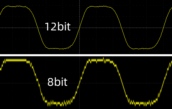
Fig. 2 Comparison of 12-bit and 8-bit waveform reconstruction
360 Mpts Deep Memory: Long-Duration Recording Without Losing Detail
When capturing complex signals over long periods, the record length directly determines how much detail remains when the waveform is zoomed in. The MO3 series supports up to 360 Mpts record length, balancing long-duration recording at large time-base settings with local detail analysis.
Segmented memory is included as standard, supporting up to 10,000 segments. For hard-to-reproduce problems such as occasional glitches, power-up anomalies, and communication frame loss, engineers can save multiple trigger events individually and quickly locate anomalies via fusion display or segment-by-segment review.
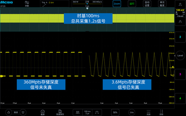
Fig. 3 Record length comparison: 360 Mpts vs. 3.6 Mpts (total acquisition time 1.2 s)
30 mm Slim Design: Fits Both Desktop and Rack Environments
At just 30 mm high, the MO3 series is easy to place on a workbench and can be integrated into space-constrained test racks. For systems that require multiple instruments, the compact design helps reduce the equipment footprint.
The product supports rack mounting and multi-unit synchronization, enabling matrix-style test environments to meet the expansion needs of complex equipment and automated test systems.
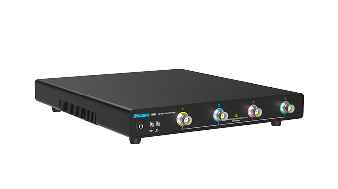
Fig. 4 MO3 series overview
Multi-Unit Synchronization: Expandable to 128 Channels
The MO3 series provides 4 analog channels and supports Trigger In/Out and 10 MHz clock In/Out. Using the MOS4 synchronizer, multiple MO3 units can achieve synchronized triggering and acquisition on up to 128 channels.
For test tasks that require synchronized observation of multiple power nodes, control signals, feedback signals, or communication links, the parallel configuration can be scaled flexibly according to the actual number of channels required.
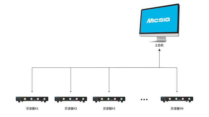
Fig. 5 Distributed expansion: one host PC controlling multiple MO3 units (#1 – #N)
HDMI Direct Connection and Remote Control: On-Site Debugging and System Integration
The MO3 series supports HDMI 1.4 direct connection to a monitor with up to 1920 × 1200 resolution. When a mouse is connected via the USB Host port, the oscilloscope can be operated directly without installing additional software — ideal for lab debugging, on-site maintenance, classroom demos, and multi-person collaboration.
The MO3 also supports PC host software, a mobile app, and SCPI commands; the Pro models support API function calls, making it easy to integrate into automated test, remote data acquisition, and customized test workflows.
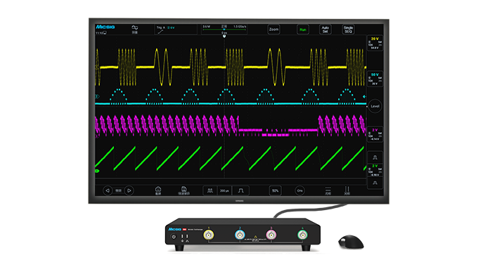
Fig. 6 HDMI direct connection: waveforms displayed on a large screen
Integrated Decoding, Analysis, and Data Storage
The MO3 series supports serial bus decoding for RS-232/422/485/UART, CAN, CAN FD, LIN, SPI, I²C, ARINC429, and MIL-STD-1553B, along with edge, pulse-width, logic, Nth edge, runt, slew-rate, timeout, video, and serial triggers.
The instrument also provides math operations, FFT (Fast Fourier Transform), high/low-pass digital filtering, and measurement statistics with analysis of up to 10,000 samples. Waveforms and results can be saved as BIN, CSV, WAV, images, or video, facilitating test records, fault reproduction, and off-line analysis.
3. Typical Application Scenarios
Power Supply and Power Electronics Testing
In testing of switched-mode power supplies, DC-DC converters, inverters, and motor drives, engineers typically need to observe switch-node, PWM, drive, feedback, and output ripple signals simultaneously.
The MO3’s 12-bit resolution and low noise floor help reveal tiny ripple and control variations, while the 500 MHz bandwidth, 3 GSa/s sample rate, and FFT analysis enable analysis of switching transients, ringing, noise spectra, and periodic interference.
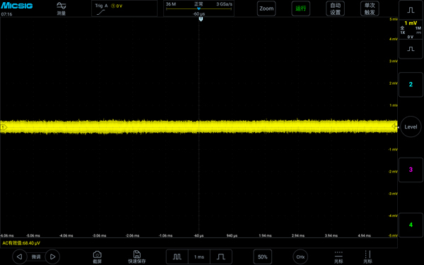
Fig. 7 Measured ultra-low base noise (flat baseline at the μV level)
Capturing Power-On Transients and Occasional Anomalies
Problems such as power-on failures, occasional glitches, relay operation, and communication frame loss usually appear only briefly under specific conditions. The MO3’s deep memory and segmented memory allow multiple trigger events to be recorded during long-duration operation.
By setting runt, pulse-width, slew-rate, or serial trigger conditions, engineers can capture abnormal waveforms more selectively and pinpoint when the problem occurred using fusion display and segment-by-segment review.
Synchronized Verification of Multi-Phase Systems and Complex Equipment
In multi-phase power supplies, power modules, motor drives, and industrial automation equipment, the waveform at a single node is usually not enough to describe the system state. The MO3 supports 4-channel synchronized acquisition and can be expanded to up to 128 synchronized channels via the MOS4 synchronizer.
This capability suits multi-phase power timing analysis, multi-node verification of power modules, co-debugging of sensors and actuators, and synchronized fault location across multi-board systems.
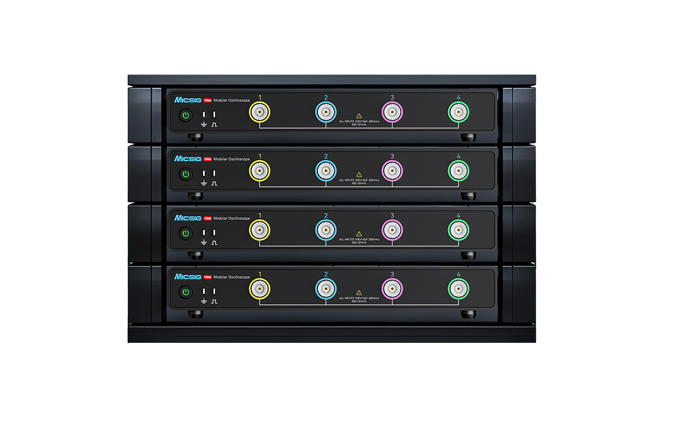
Fig. 8 Multiple MO3 units stacked vertically, ideal for building a matrix test environment
Embedded Systems and Bus Debugging
For industrial control, embedded devices, and communication modules, engineers need to evaluate physical-layer waveforms, timing relationships, and protocol data content at the same time.
The MO3’s serial triggering and bus decoding capabilities can be used to debug and locate faults in CAN, CAN FD, LIN, SPI, I²C, UART, ARINC429, and MIL-STD-1553B signals. Decoded data supports TXT display and CSV export, making it easy to build test records and perform follow-up analysis.
Automated Testing and System Integration
The MO3 supports SCPI, host PC control, LAN, USB, Trigger In/Out, and 10 MHz clock synchronization; the Pro models also provide an open API library for secondary development and deep system integration, allowing the oscilloscope to serve as a waveform acquisition node in automated test systems.
Pro models provide an SFP+ high-speed optical port and a test-system integration software package, suitable for applications with higher demands on high-speed data streaming, multi-device collaboration, and test system development.
4. Model Selection Guide
Model | Recommended Applications |
MO34-250 / MO34-250Pro | Industrial control, bus debugging, general power supply testing, automated equipment R&D |
MO34-350 / MO34-350Pro | Motor drives, power electronics, communications R&D, high-speed control signal analysis |
MO34-500 / MO34-500Pro | High-speed switching, power supply transients, high-frequency signals, and precision waveform analysis |
Pro Models | Automated testing, remote acquisition, multi-device collaboration, and test system integration |
Summary
The Micsig MO3 series high-resolution modular oscilloscope does more than pack bandwidth, sample rate, and record length into a single instrument. Through 12-bit high resolution, a low noise floor, deep memory, segmented acquisition, multi-unit synchronization, and system integration capabilities, it provides complete support for complex test tasks.
From power ripple and switching transient analysis to occasional anomaly capture, multi-channel timing verification, bus debugging, and automated test system development, the MO3 series helps engineers observe waveforms more clearly and locate problems more efficiently.
The Micsig MO3 series — see the details with high resolution, expand the boundary of testing with modularity.