How to Choose the Right Oscilloscope Bandwidth
Release Time:2026-09-30
When selecting an oscilloscope, bandwidth is the first specification to look at. Two common mistakes appear during selection: chasing the highest bandwidth blindly, or judging by a single number. Too little bandwidth distorts waveform details and rounds off rising edges; too much raises cost and noise. Starting from the fundamentals, this article gives you a practical, actionable method for choosing bandwidth.
1. First, Understand: What Exactly Is Oscilloscope "Bandwidth"?
The bandwidth of an oscilloscope is the frequency at which a sine wave, after passing through the oscilloscope's front end, is attenuated to -3 dB (about 0.707×) of its true amplitude. It defines the upper frequency limit that a scope can "faithfully reproduce". Beyond this frequency, signal amplitude is progressively reduced:
· A 1 V, 200 MHz sine wave measured with 200 MHz bandwidth → only about 0.707 V remains
· The higher the frequency, the greater the attenuation, and the more "flattened" the high-frequency details become
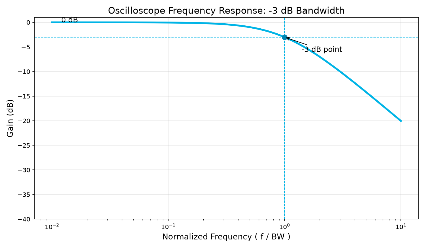
Note: theoretical frequency response curve based on the oscilloscope -3 dB bandwidth definition.
2. Bandwidth and Rise Time: the 0.35 Rule
For an oscilloscope with a Gaussian response (-3 dB bandwidth), bandwidth and rise time are approximately related by:
Rise time tr ≈ 0.35 / Bandwidth
Plugging in a few common values: 500 MHz → rise time ≈ 0.7 ns; 1 GHz → ≈ 0.35 ns. The 0.35 coefficient applies to Gaussian-response systems; for instruments with different frequency-response characteristics the coefficient ranges from 0.35 to 0.45 — refer to the manufacturer's datasheet for specifics.
This tells us: bandwidth determines how fast a signal edge you can measure. If the signal's rising edge is faster than the oscilloscope's own rise time, the edge you see is artificially "rounded" — measured rise time reads high and amplitude reads low. So when choosing bandwidth, don't just look at signal frequency; look at the edge speed of the signal itself — especially for digital signals. A more commonly used engineering formula: when the oscilloscope's rise time is only 1/3 of the signal's, measurement error is about 5% — so the scope's rise time should be clearly faster than the signal edge being measured.
3. How to Choose Bandwidth: Three Rules of Thumb
· Rule 1: For sine-like signals, use 3–5× the highest frequency. For signals dominated by a fundamental, such as sine waves, a bandwidth of 3–5× the signal's highest frequency ensures amplitude accuracy; the higher the multiple, the smaller the amplitude error.
· Rule 2: For square waves, capture at least the 5th harmonic. A square wave is built from the fundamental plus many harmonics; to see a "true square wave", at least 5 harmonics must be reproduced. For example, a 40 MHz square wave typically needs about 200 MHz of bandwidth; with insufficient bandwidth the square wave degenerates into a rounded shape and edge information is lost.
· Rule 3: Derive bandwidth from rise time. For high-speed digital signals, look up (or estimate) the signal's rise time tr from the device datasheet, then apply BW ≈ 0.35 / tr, with roughly 2× margin.
Combine the three: first identify the signal type → estimate the fundamental / harmonics / rise time → derive the required bandwidth. One reminder: bandwidth is only the first filter — sample rate and noise floor are the next two gates before selection is complete.
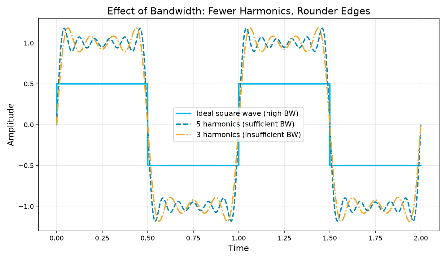
Note: drawn from the Fourier series expansion of a square wave, comparing waveforms with different harmonic truncation (illustrative).
4. Bandwidth and Sample Rate: Inseparable Partners
Once bandwidth is chosen, sample rate must be considered too. By the Nyquist sampling theorem, reconstructing a signal requires a sample rate at least twice the signal's highest frequency; in engineering practice, to guarantee waveform reconstruction quality, the oscilloscope's real-time sample rate is typically recommended at about 5× the bandwidth (oversampling), with the exact multiple depending on signal complexity.
With insufficient sample rate, "aliasing" occurs — high-frequency components are disguised as low-frequency artifacts, and waveforms that don't exist at all appear on screen. So when judging an oscilloscope, always evaluate bandwidth × sample rate together; the two must match. Also note: on some models the per-channel sample rate is halved when multiple channels are enabled simultaneously, so calculate using the worst case; if aliasing is suspected, adjust the timebase or switch on bandwidth limiting — if the frequency reading changes abnormally, aliasing is basically confirmed.
5. The Key Trade-off: Wider Bandwidth, Higher Noise
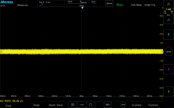
This is the most easily overlooked point: the wider the bandwidth, the higher the noise floor (noise grows roughly with the square root of bandwidth). So bandwidth is not "the wider the better" — a truly excellent high-bandwidth oscilloscope achieves both "wide bandwidth + controlled noise". A wide-bandwidth scope with a high noise floor still can't see weak signals. That's why the emphasis today is on evaluating "bandwidth + vertical resolution / noise floor" together rather than a single number. Take the Micsig MHO3 series as an example: at full 500 MHz bandwidth, the measured noise floor is only 68.49 μVrms (see below) — weak signals remain clear and stable.
6. Don't Forget: System Bandwidth Is Set by the Weakest Link
An oscilloscope's rated bandwidth is that of the mainframe, but what actually reaches the screen is the system bandwidth of the entire "probe + mainframe" chain — determined by the weakest link. If the probe's bandwidth is insufficient, no amount of mainframe bandwidth helps; in general the probe's system bandwidth should be no lower than the mainframe's, and for high-voltage, high-speed switching signals, pay extra attention to the probe's bandwidth margin and ground-lead loop. Micsig's high-voltage differential probes, MOIP optical isolated probes, Rogowski coils, and high-frequency current probes pair directly with the MHO series — choose the right probe for the signal, and only then is the mainframe's bandwidth fully utilized.
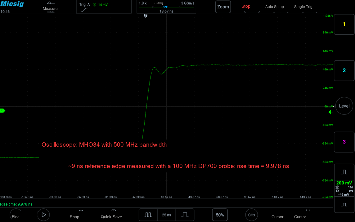
Note: a ~9 ns fast edge measured with a 500 MHz oscilloscope + 100 MHz probe; measured rise time 9.978 ns.
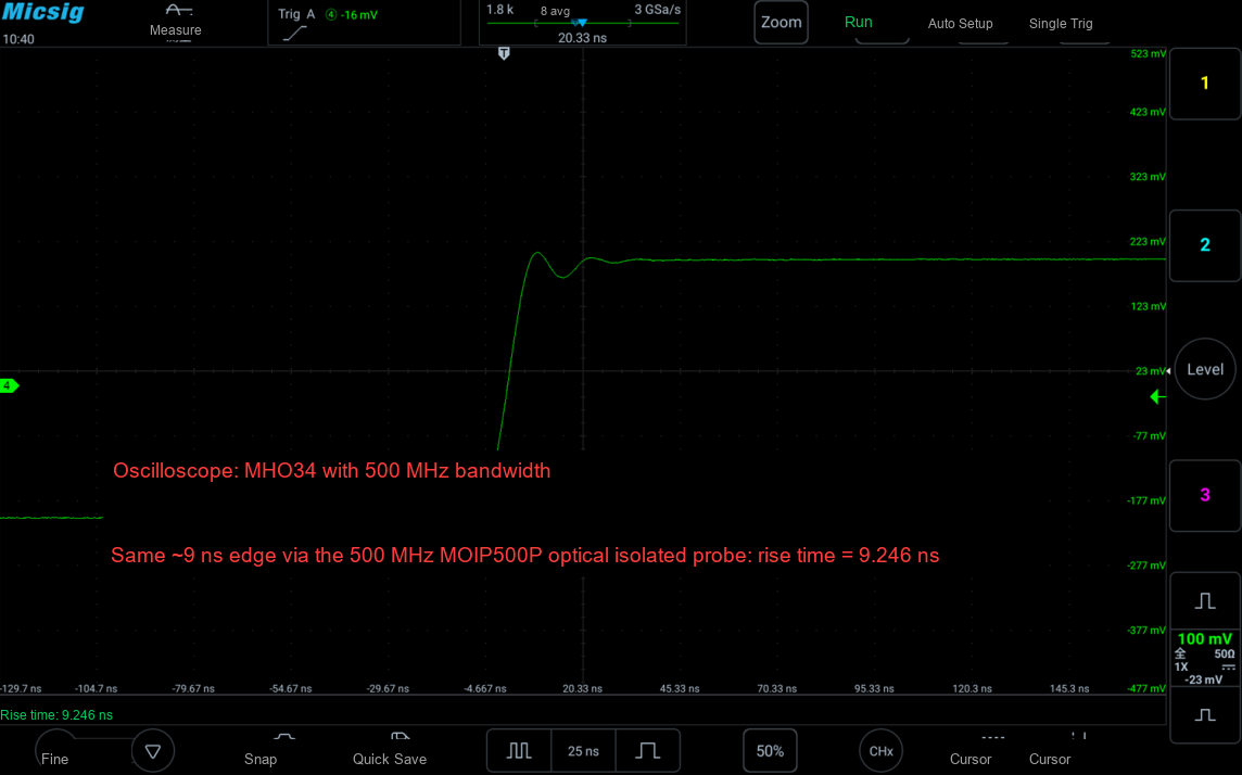
Note: the same signal measured with a 500 MHz oscilloscope + 500 MHz optical isolated probe; measured rise time 9.246 ns.
7. The MHO Series as an Example: How Much Bandwidth Counts as "Chosen Right"?
Take the Micsig MHO series of high-resolution oscilloscopes: its bandwidth, sample rate, and noise are designed as a whole, making it a good case for understanding "how to choose":
Key Point | How the MHO Series Does It |
Full bandwidth lineup | MHO3 series offers 250 MHz / 350 MHz / 500 MHz; MHO6 series offers 350 MHz / 500 MHz / 1 GHz — choose by signal needs without wasting budget |
Bandwidth × sample rate matched | MHO3 (500 MHz / 3 GSa/s), MHO6 (1 GHz / 6 GSa/s): real-time sample rate at the highest bandwidth tier is about 6× the bandwidth (higher multiples at lower tiers) — ample oversampling |
Wide bandwidth, low noise | MHO3 keeps its noise floor below 80 μVrms even at full 500 MHz bandwidth — wide bandwidth without giving up noise control |
High resolution on top | A 12-bit ADC (4096 quantization levels) keeps small details visible even at high bandwidth, ideal for power supplies and power devices |
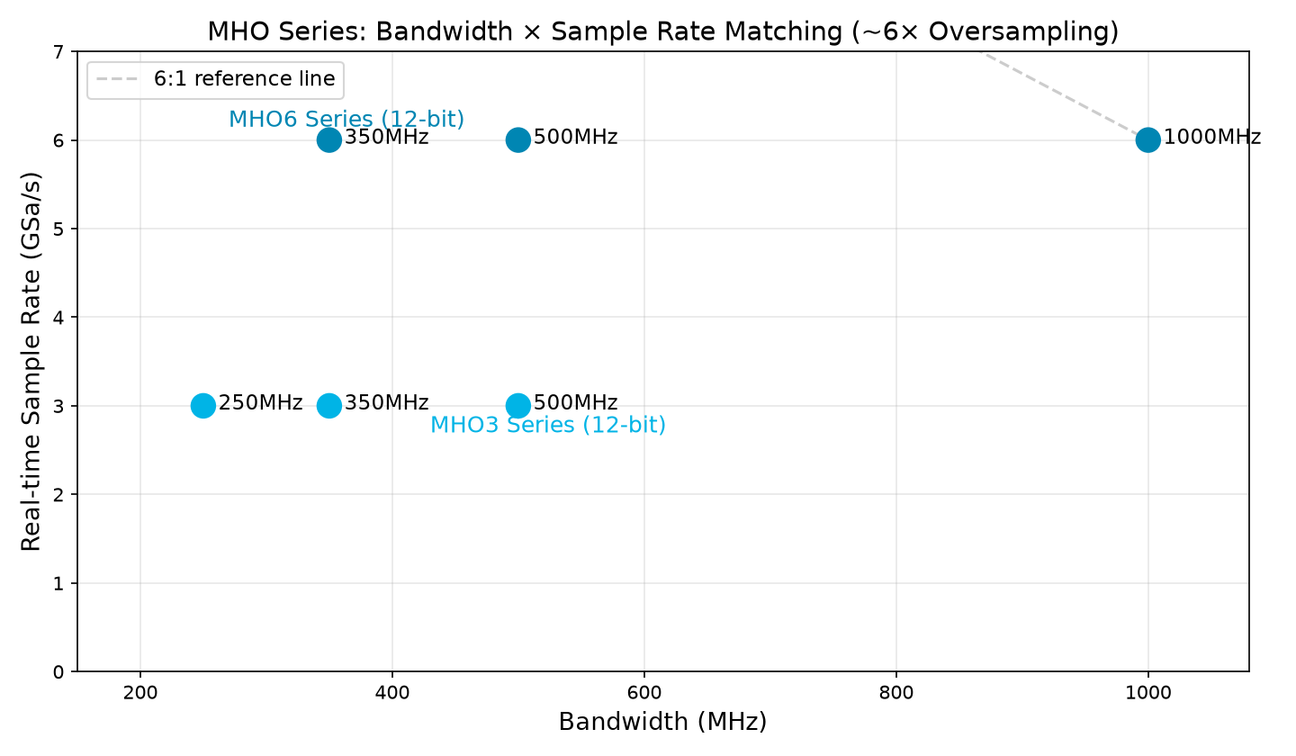
Note: data source — MHO series product specifications on the Micsig official website.
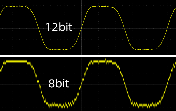
Note: 12-bit vs 8-bit waveform reconstruction comparison — with high resolution, small-signal details are no longer buried under quantization steps.
8. One Table to Help You Decide
Your Application | Recommended Bandwidth | Key Considerations |
Power-supply ripple, low-frequency signal measurement | 100–250 MHz | Focus on noise floor and small signals; just enough bandwidth |
MCU debugging, serial buses, IGBT power circuits | 200–500 MHz | Rule of thumb: bandwidth ≥ 5× the signal's highest frequency |
High-speed serial links, SiC/GaN | 500 MHz–1 GHz+ | Watch rise time; bandwidth and sample rate must both be met |
Summary
Bigger is not always better — bandwidth should be "sufficient + matched": enough to reproduce your signal's frequency and rising edges, with sample rate keeping up and noise floor under control. Only then have you truly chosen right.
Want help matching a bandwidth tier to your test scenario? Leave your signal type and bandwidth questions in the comments — we'll answer each one; you can also contact Micsig through the official website to arrange a demo evaluation with a sample unit.