The "Three Workhorses" of Power Device Current Measurement: Rogowski Coil vs. Coaxial Shunt vs. High-Frequency Current Probe
Release Time:2026-09-02
In the SiC/GaN era, switching speeds are faster, currents are larger, and bus voltages are higher. Inaccurate current measurement directly undermines the conclusions of double-pulse testing, loss evaluation, and reliability validation. This article compares the technical characteristics and application boundaries of the three mainstream current measurement approaches and provides a practical selection path.
Introduction: Why Current Measurement Becomes the Bottleneck in Power Device Testing
In double-pulse testing, measured switching losses exceed datasheet values by 30% and differ from one setup to another; in short-circuit testing, kilo-ampere currents cause probe magnetic saturation and waveform clipping; when measuring the low-side device of an SiC half bridge, connecting a conventional probe into a high-voltage floating circuit risks a short circuit. These problems often originate not in the device under test, but in the current measurement chain itself.
Power device switching speeds have entered the nanosecond range, currents reach kilo-ampere levels, and bus voltages span 800 V–1700 V. Mainstream current measurement approaches fall into three categories: Rogowski coils (di/dt sensing + integration, no magnetic saturation), coaxial shunts (precision sampling by I = V / R, the accuracy benchmark), and high-frequency AC/DC current probes (Hall effect + current transformer, convenient clamp-on). This article analyzes each approach in the order of principle → advantages → limitations → applications, and provides a practical selection path.
01 Rogowski Coils: The First Choice for High-Current Transient Measurement
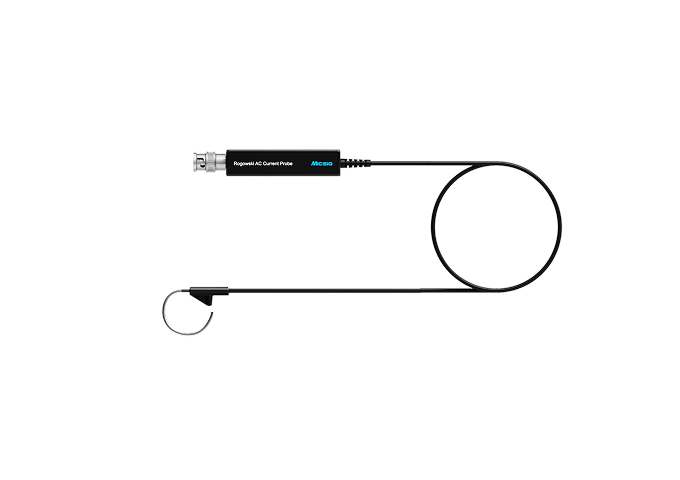
Micsig RCP series Rogowski coil current probe
Principle: An air-core coil encircles the conductor under test, senses the di/dt signal, and restores the current through integration. The coreless structure is inherently free of magnetic saturation and introduces no insertion loss.
Key Advantages | Key Limitations |
No magnetic saturation; measures kilo-ampere short-circuit/surge currents; first choice for SCWT | No DC capability; low-frequency cutoff around 10 Hz; droop |
Inherent electrical isolation for high-voltage floating applications | Accuracy 1%–3%; affected by conductor position within the coil |
Flexible coil encircles busbars/heavy cables without altering the circuit under test | Integrator drift and phase error require calibration |
Typical applications: short-circuit withstand (SCWT), lightning surge, high-current transients, high-voltage floating current
Summary: For kilo-ampere high-current transient measurement, a Rogowski coil is the first choice.
02 Coaxial Shunts: The Benchmark for Precision Laboratory Measurement
Principle: A low-inductance precision sampling resistor produces a voltage drop as the current flows through it, and the current is restored by I = V / R. The coaxial structure reduces parasitic inductance to the sub-nanohenry level, providing excellent high-frequency performance.
Key Advantages | Key Limitations |
Accuracy 0.1%–1%; the industry benchmark for switching loss/efficiency calibration | Must be inserted in series; heats up at high currents, alters circuit characteristics, and adds parasitic inductance |
Flat frequency response and excellent phase characteristics; minimal power integration error | High floating-ground risk; connecting directly to an oscilloscope creates a ground loop |
Supports DC; essential for precision measurements such as dynamic Rds(on) | Requires an optically isolated probe; otherwise there is a risk of equipment damage |
Typical applications: double-pulse switching loss, dynamic Rds(on), efficiency/power calibration
Summary: Choose a shunt when accuracy is the top priority, and always pair it with an isolated measurement solution.
03 High-Frequency AC/DC Current Probes: The Universal Solution for Field Debugging
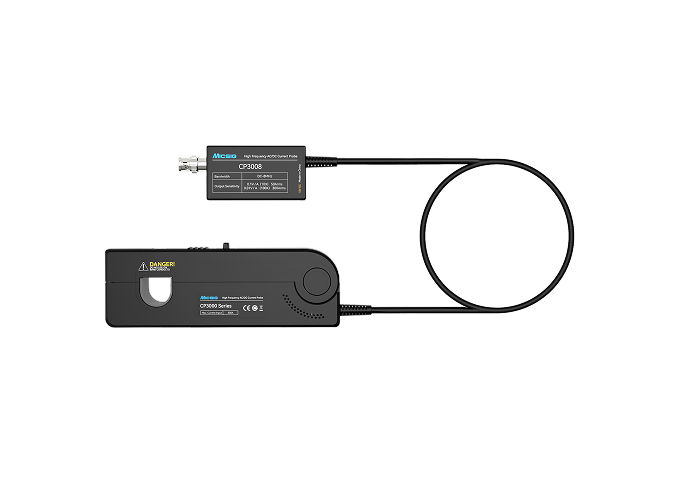
Micsig CP3008 high-frequency AC/DC current probe
Principle: A Hall-effect element measures the DC and low-frequency components, while a current transformer measures the high-frequency AC component; the two paths are combined into a wideband AC/DC waveform. This is the most widely used approach in field engineering.
Key Advantages | Key Limitations |
Full AC/DC frequency coverage (DC to several MHz); clamp on and measure | Standard models (e.g., CP3008) offer a bandwidth of about 8 MHz; to fully reproduce higher-frequency signals such as SiC nanosecond edges, higher-bandwidth models are available, e.g., CP1510 (10 MHz), or professional high-frequency models CP503B (50 MHz) / CP1003B (100 MHz) |
Non-invasive clamp-on design; does not change circuit impedance; high test efficiency | Magnetic saturation risk; out-of-range waveforms are clipped |
Safe electrical isolation; one-button degauss and auto-zero | Accuracy 1%–3%; not as good as shunts for precision loss measurement |
Typical applications: motor drives, switching power supplies, inverters, EV charging stations, general debugging
Summary: For general-purpose measurement balancing convenience, safety, and moderate accuracy, a high-frequency current probe is the right choice.
04 Side-by-Side Comparison: Key Parameters
Parameter | Rogowski Coil | Coaxial Shunt | High-Frequency AC/DC Probe |
Measurement Principle | di/dt sensing + integration | I = V / R | Hall effect + current transformer |
Bandwidth | 2 Hz – 30 MHz | DC – hundreds of MHz to 2 GHz | DC – 10 MHz to 100 MHz |
DC measurement | Not supported | Supported | Supported |
Accuracy | 1%–3% | 0.1%–1% (benchmark) | 1% |
Electrical isolation | Inherent | None; high floating-ground risk | Inherent |
Series insertion | No (encircling) | Yes (in series) | No (clamp-on) |
High-current saturation | No saturation | No saturation, but heats up | Saturation risk |
Phase characteristics | Moderate; calibration required | Excellent | Moderate |
Convenience | Requires encircling + integrator | Requires insertion + isolation solution | Clamp-on and measure |
Typical applications | Short-circuit / surge / transient | Double-pulse / dynamic Rds(on) | Motor / power supply / field |
Key takeaway: There is no absolute winner among the three — it all comes down to matching the right tool to the requirement. Accuracy, isolation, bandwidth, and convenience cannot all be maximized at once.
05 Selection Guide: Recommended Solutions for Six Typical Scenarios
1. Kilo-ampere transients such as SCWT and lightning surge: Rogowski coil. Freedom from magnetic saturation is the key criterion — conventional current probes may saturate, clip, or even be damaged.
2. Precision measurement of double-pulse, switching loss, and dynamic Rds(on): coaxial shunt + optically isolated probe; if efficiency matters more, fall back to a Rogowski coil + phase calibration.
3. Motor phase current, power bus, and EV charging station field debugging: high-frequency AC/DC current probe. Choose a large jaw opening (≥20 mm) for high currents and a high-bandwidth model for high-frequency applications.
4. High-voltage floating measurements (e.g., the low-side device of an SiC half bridge): prefer a Rogowski coil (inherent isolation); if a shunt is used, it must be paired with an optically isolated probe to avoid ground loops.
5. Small-current detail measurement (standby power, control circuits): a low-range current probe plus a 12-bit oscilloscope is required to reveal mA-level detail.
6. When waveforms look normal but the measurement chain needs verification: perform de-skew alignment and bandwidth matching. Probe delay is typically 40 ns; without alignment, loss integration errors can reach double-digit percentages. The sampling rate should be at least four times the bandwidth.
The often-overlooked "fourth workhorse" is the measurement chain itself: probe delay, oscilloscope bandwidth, vertical resolution (8-bit vs. 12-bit), and record length. Insufficient bandwidth loses high-frequency energy (making losses appear too small), while misaligned phase introduces integration errors (making losses appear too large) — this is exactly why "changing the measurement setup yields different results."
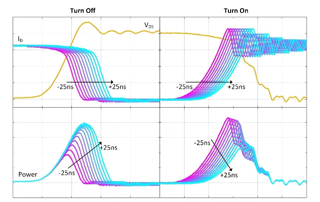
Top: V_DS (yellow) and I_D (purple/cyan) waveforms overlaid at different delay skews; bottom: the corresponding instantaneous power P = V_DS × I_D. A ±25 ns skew is enough to cause significant differences in Eon/Eoff.
06 The Micsig Solution: A Complete Current Measurement Portfolio
Rogowski Coils: RCP Series Flexible Current Probes (AC)
Model | Bandwidth | Range | Accuracy | Features |
RCP300XS | 10 Hz – 30 MHz | 300 Apk | ±2% | Slew rate 20 kA/µs; coil cross-section 1.6 mm |
RCP600XS | 8 Hz – 30 MHz | 600 Apk | ±2% | Slew rate 40 kA/µs; first choice for short-circuit testing |
The RCP series is dedicated to AC current measurement (DC not supported), covering short-circuit testing, surge, and high-voltage floating applications. The XS series coil has a cross-section diameter of only 1.6 mm and can encircle conductors with a 25 mm inner diameter; loop circumference and lead length are customizable.
Note: The RCP series includes multiple sub-series — XS, S, M, L, etc. — covering peak currents from 60 Apk to 12,000 Apk with bandwidth up to 30 MHz. Only two representative XS models are listed above; for complete selection information, please visit the Micsig official website or request the product catalog.
High-Frequency AC/DC Current Probes: CP Series
Model | Bandwidth | Range | Accuracy | Features |
CP1510 | DC – 10 MHz | 30 A / 150 A 150 Arms / 300 Apk | ±1% | 20 mm jaw; rise time ≤46 ns; fastest high-frequency response among high-current models |
CP3008 | DC – 8 MHz | 50 A / 300 A dual range 300 Arms / 500 Apk | ±1% | 20 mm jaw; 10 mA resolution on 50 A range, 100 mA on 300 A range |
CP3005 | DC – 5 MHz | 50 A / 300 A dual range 300 Arms / 500 Apk | ±1% | Same ranges as CP3008; cost-effective option |
High-current models in the CP high-frequency series come standard with: a 20 mm jaw opening (CP3008/3005/1510), ±1% accuracy, overload and jaw-status indicators, and a standard BNC interface compatible with oscilloscopes of all brands.
Note: The CP series also includes CP503B (DC–50 MHz, 5 A/30 A, 5 mm jaw) and CP1003B (DC–100 MHz, 5 A/30 A, 5 mm jaw) for small-current, high-frequency testing applications.
Isolation Companion for Coaxial Shunt Solutions: MOIP Optically Isolated Probes
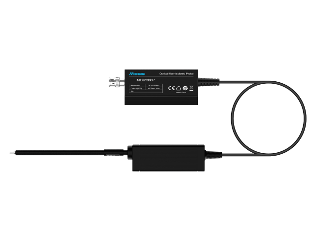
Micsig MOIP optically isolated probe
Although coaxial shunts are highly accurate, floating-ground and common-mode interference limit their applications. The Micsig third-generation SigOFIT optically isolated probe, the MOIP series (laser-powered, 200 MHz–1.2 GHz bandwidth, 85 kVpk common-mode voltage), achieves a common-mode rejection ratio of up to 180 dB at DC, allowing a shunt to measure voltage safely and accurately near high-voltage switching nodes — the core of the "shunt + optically isolated probe" approach to floating-ground measurement.
Foundation Platform for the Measurement Chain: MHO6 Series High-Resolution Oscilloscopes
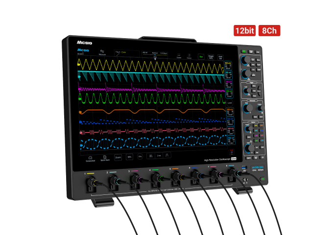
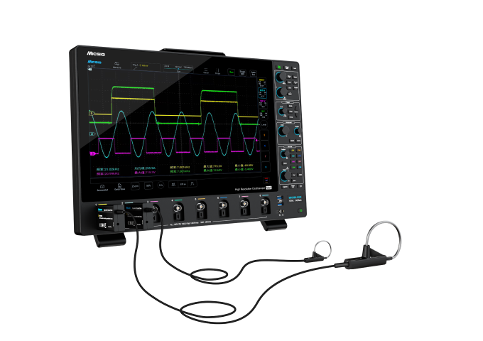
Micsig MHO6 series high-resolution oscilloscope
12-bit vertical resolution + 1 GHz bandwidth + 6 GSa/s sampling rate + 1800 Mpts record length + 8-channel synchronization: 12-bit resolution reveals mA-level small-current detail; 8 channels support simultaneous measurement of multi-phase currents and multiple gate-drive signals; the 1800 Mpts deep record ensures long-duration high-frequency waveform capture without losing detail.
Quick Reference: Recommended Configurations
Test Requirement | Recommended Combination |
Short-circuit withstand (SCWT) | RCP600 (saturation-free high current) + MHO6 series |
Double-pulse switching loss | Shunt + MOIP optically isolated probe (or RCP + phase calibration) |
Dynamic Rds(on) | Shunt + MOIP optically isolated probe + 12-bit oscilloscope |
Motor / inverter / charging station | CP3008 (large jaw) + MHO6 series |
SiC/GaN high-voltage floating | RCP Rogowski coil (isolated) or shunt + MOIP |
Standby-power small current | CP3008 low range (10 mA resolution) + 12-bit oscilloscope |
Conclusion
Kilo-ampere high-current transients → Rogowski coil; precision loss and efficiency measurement → coaxial shunt + optically isolated probe; general-purpose measurement balancing convenience and safety → high-frequency AC/DC current probe.
The three approaches complement one another — Micsig RCP + CP + MOIP + MHO6 form a complete solution for power device current measurement.
Note: The data in this article is based on public sources and typical test conditions. For detailed specifications, selection recommendations, and the latest product catalog, please visit the Micsig official website or leave a message.