From 8 Bits to 12: How Vertical Resolution Determines Measurement Accuracy
Release Time:2026-11-09
1. Where the Problem Starts: Signals Are Smaller — and More Crowded
Switch-mode power supply output ripple has shrunk from tens of millivolts to the low teens or even single-digit millivolts; on the gate plateau of a SiC or GaN device, what really decides drive quality is a step of a few hundred millivolts buried in a ten-plus-volt signal; in light-load standby, the target is a faint fluctuation riding on milliamp-level DC.
These trends create two kinds of difficulty. First, absolute signal amplitudes keep sinking. Second, small signals often ride on top of large ones — next to the gate plateau sits a 30 V turn-off overshoot; beside a subtle current ripple sits a load step of several amperes. The second case is the nastier one: to avoid clipping the waveform, the vertical scale must give the large signal nearly the whole screen, and the small signal is left with only a thin slice of the quantization levels.
Measurement accuracy therefore comes down to two things: how many quantization levels the small signal can claim, and whether link noise washes away the extra levels you fought for.
Start with the first.
2. The First Factor: Bit Depth Sets How Fine the Steps Can Be
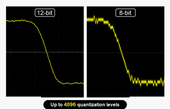
Figure 1The same signal reconstructed at 12 bits vs. 8 bits: quantization levels rise from 256 to 4,096
2.1 From 256 Levels to 4,096
The ADC bit count N sets the number of quantization levels across the full screen: 256 for 8 bits, 4,096 for 12 bits — 16 times as many, worth about 24 dB of quantization-noise improvement. This gap does not depend on the volts-per-division setting; it depends only on the ratio between the large and the small signal. Take a 5 V/div screen (40 V full-screen) that has to accommodate a 30 V turn-off overshoot: 1 LSB is 156 mV at 8 bits versus 9.8 mV at 12 bits. The same 0.5 V plateau gets only 3 codes in the former but 51 codes in the latter. Three codes do not make a plateau; fifty-one codes reveal both its height and its slope. Changing the vertical scale does not help — what matters is always the 40 V : 0.5 V = 80:1 ratio.
2.2 Four Advantages over 8-Bit Oscilloscopes
Smaller quantization error. On the same 40 V full screen: worst-case quantization error is about ±78 mV for an 8-bit scope versus about ±4.9 mV for a 12-bit scope, and quantization noise falls from roughly 45 mVrms to about 2.8 mVrms.
Small-signal detail becomes readable. The same arithmetic applies to current: with a 1 V/A current probe measuring 20 mA peak-peak ripple on a screen that must also show a 4 A load step, full screen is 4 A — at 8 bits the 20 mA occupies barely more than one code, a jittery thick line; at 12 bits it gets about 20 codes, enough to read both slope and envelope. The precondition is a 20 MHz bandwidth limit and proper degauss/auto-zero.
Resolution no longer trades against bandwidth and capture rate. An 8-bit architecture can only raise resolution through averaging or high-resolution acquisition: averaging 4 samples buys 1 bit, and reaching 4 extra bits requires averaging 256 — which demands a strictly repetitive signal and drags the waveform update rate down; high-resolution mode trades bandwidth for bits. A hardware 12-bit ADC needs no such trade — the resolution is already in the ADC, leaving bandwidth and capture rate untouched.
Readable even at large dynamic range. Across the combined scenarios above, 12 bits makes “no clipping” and “clearly visible” true at the same time — something an 8-bit scope cannot deliver in an 80:1 situation.
Table 1Scene-by-scene comparison
Scenario | 8-bit performance | 12-bit + full link (MHO6 + MOIP) |
Power-supply output ripple (a few mV on tens of volts of DC) | Needs AC coupling and bandwidth limiting; the DC offset is removed along with it | DC stays on screen; ripple peak-peak and frequency content read out in one shot |
SiC / GaN gate plateau (0.5 V step / 30 V overshoot) | The step is quantized into 3 codes; the plateau looks like a flat line | 51 codes; plateau slope and crosstalk steps are measurable |
Current ripple (20 mA / 4 A step) | A jittery thick line | About 20 codes; envelope clearly visible |
Standby burst envelope (milliamps / load steps) | Top fluctuation and quantization steps blur together | Clean outline; width and amplitude readable |
3. The Second Factor: Noise Decides How Many Bits You Actually Get
All of the above only counts the bit-depth side of the ledger. However many quantization levels you have, they are wasted once noise covers them. Engineering practice uses effective number of bits (ENOB) to measure the bits that are actually usable — derived from SINAD as ENOB = (SINAD − 1.76) / 6.02, which counts noise, distortion, and nonlinearity together, so it normally falls below the nominal figure. The real test of a “12-bit scope,” then, is not the bit count but how many usable bits survive across the entire chain.
It is equally fair to say 12 bits is not omnipotent: if no large signal is on screen, a finer vertical scale is enough; and if the bottleneck lies in probe noise or gain accuracy, the extra bits will not cash in either.
4. Solving Both at Once: The Micsig Approach
4.1 Full Bit Depth: High Vertical Resolution in the Oscilloscope
On the mainframe side, Micsig's 12-bit high-resolution line spans benchtop, modular, and portable tablet form factors — the MHO6, MHO3, MO3, MHO1, and STO series are all built on hardware 12-bit ADCs. Two highlights:
The MHO6 series — the highest bandwidth and channel count: 8 analog channels, three bandwidth tiers of 350 MHz / 500 MHz / 1 GHz (rise times ≤1 ns / ≤0.7 ns / ≤0.4 ns respectively), up to 6 GSa/s real-time sampling and 1.8 Gpts maximum memory depth, with a waveform capture rate of up to 280,000 wfms/s — well suited to multi-channel synchronized system-level testing.
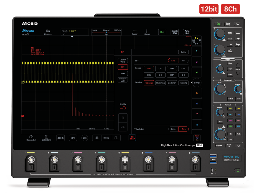
Figure 2MHO6 series: 12-bit ADC, 8 analog channels, 6 GSa/s real-time sampling
The MHO1 series (MHO14-100 / MHO14-200) — 12 bits in a portable form: an 8-inch tablet body just 3.1 cm thick, 100 MHz / 200 MHz bandwidth, 4 channels, 1 GSa/s real-time sampling, 110 Mpts memory depth, a large built-in lithium battery and an optional multimeter function — made for on-site debugging and field testing.
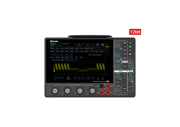
Figure 3MHO1 series (MHO14-100 / MHO14-200): 12-bit ADC, 4 channels, 1 GSa/s, 110 Mpts, 8-inch portable tablet
4.2 Suppressing Common-Mode Interference: MOIP Optical-Fiber Isolated Probes
Whether the resolution pays off also depends on the probe side. A floating gate often carries common-mode swings of tens of volts: with a probe CMRR of only 60 dB, a 30 V common-mode step couples in about 30 mV — roughly 3 codes on a 12-bit scope at 40 V full screen — swamping the very step you are trying to resolve. The third-generation SigOFIT™ MOIP delivers a CMRR of 180 dB at DC and still 106 dB at 1.2 GHz; under the same conditions less than 0.2 mV couples in — under 1 code. Its noise floor goes as low as <0.3 mVrms (models at 500 MHz and below), leaving the low-order codes intact; input capacitance is as low as 1 pF, and DC gain accuracy is 1%.
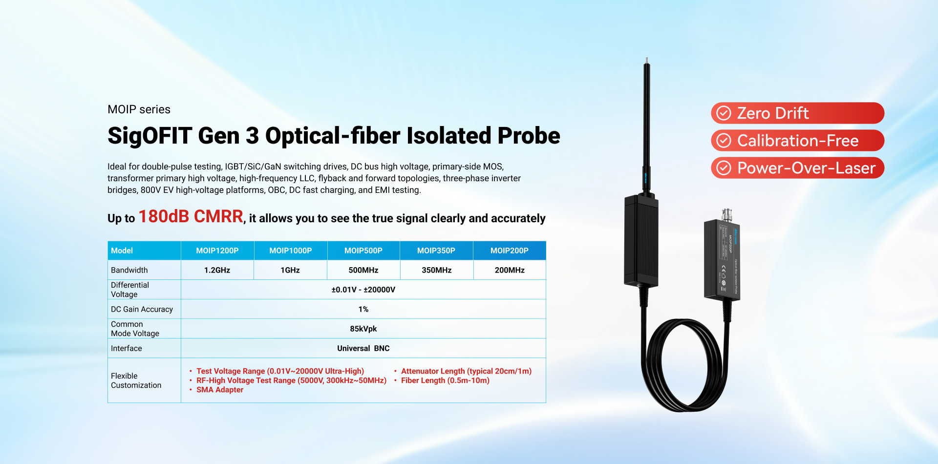
Figure 4Third-generation SigOFIT™ MOIP series optical-fiber isolated probes (200 MHz – 1.2 GHz)
5. Summary
ADC bit depth sets how finely the quantization ladder can be subdivided, while the system noise floor decides whether each level can be reliably cashed in; together they determine how many resolvable levels a small signal gets in a single acquisition. Micsig addresses the two in one coordinated design: the oscilloscope's hardware ADC natively delivers 12-bit resolution without trading away bandwidth or capture rate, while the MOIP optical-fiber isolated probe blocks common-mode interference and noise at the signal input, protecting the effective use of the low-order codes. For 80:1 dynamic-range conditions, the core gain of this approach is making weak signals that were previously unmeasurable measurable.
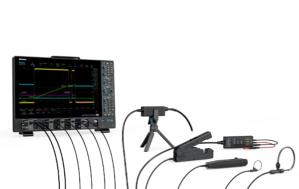
Figure 5A complete measurement chain: mainframe, optical-fiber isolated probe, and current probes
Code counts and error figures in this article are idealized model estimates; for product specifications, refer to the latest datasheets on the Micsig official website.